Drive Alert (Yaskawa)
| Serial number | Drive Alert | Diagram | Normal operating standards | Failure Analysis | Exception handling solution |
|---|---|---|---|---|---|
| 1 | A.710 Overload |  | bb/run | Instantaneous maximum load) Operation with a torque significantly exceeding the rated value for several seconds to tens of seconds. | Confirm that the motor wiring and encoder wiring are Is there a problem? Improve mechanical factors. Servo unit failure. Replace Servo unit. |
| 2 | A.720 Overload |  | bb/run | (Continuous maximum load) Continuous operation was performed with a torque exceeding the rated value. | Confirm that the motor wiring and encoder wiring are Is there a problem? Improve mechanical factors. Servo unit failure. Replace Servo unit. |
| 3 | A.F10 |  | bb/run | Power line phase loss When the main power is on, the voltage of one of the R, S, or T phases is too low for more than 1 second. | Check whether there is any problem with the power wiring. Correct the imbalance of the power supply (switch phases). Set the correct power input and parameters. Reconnect the power supply and the alarm still occurs The servo unit may be faulty. Replace the servo unit |
| 4 | A.7AB |  | bb/run | The fan inside the servo unit stops. Check whether there is any foreign object stuck in it. | If the alarm still occurs after removing the foreign object, The servo unit may be faulty. Replace Servo unit. |
| 5 | A.C90 |  | bb/run | Encoder communication fault The encoder connector has poor contact or the connector is wired incorrectly. Check the encoder connector status. Insert the encoder connector again and check the encoder wiring. The encoder cable is broken, short-circuited, or a cable with an impedance exceeding the specified value is used. Check the encoder cable status. | Correctly wire the encoder peripherals (Separate the encoder cable from the servo motor Main circuit cable, grounding treatment, etc.). |
| 6 | A.910 |  | bb/run | Overload pre-alarm is a warning display before reaching overload alarm (A.710 or A.720). If the operation continues, an alarm may occur. | Overload pre-alarm is a warning display before reaching overload alarm (A.710 or A.720). If the operation continues, an alarm may occur. |
Drive Alarm (Panasonic)
| Serial number | Drive Alert | Diagram | Normal operating standards | Failure Analysis | Exception handling solution |
|---|---|---|---|---|---|
| 1 | 16.0 |  | 0.0 | Overload protection (U/V/W cable connector is loose. Brake BK protection is not enabled. | Check if the cable connection is correct and remove any loose cables. Check whether the 24V power supply is connected normally |
| 2 | 21.0 |  | 0.0 | The encoder cable is disconnected (one of the encoder cables is disconnected) | Check if the cable connection is correct and remove any loose cables. |
| 3 | 40.0 |  | 0.0 | Absolute system shutdown protection | The battery voltage in the battery box is lower than 3.6V. Disconnect the battery from the driver and motor and reconnect them. The absolute encoder needs to be reset. |
Drive alarm (Weihong)
| Serial number | Drive alarm | Diagram | Operation Standard | Inspection Tools | Abnormal maintenance method |
|---|---|---|---|---|---|
| 1 | Err 16.0 Overload protection |  | Pulse Digital | Poor gain adjustment causes oscillation and vibration. The motor vibrates and makes abnormal sounds. The setting value of the inertia ratio Pr004 is abnormal. Motor wiring is incorrect or wires are broken. The machine is hit or the load suddenly becomes heavier, causing twisting and winding. | Connect the motor wires correctly according to the wiring diagram. Replace the cable. Eliminate entanglement. Reduce load. Connect the motor cable and encoder cable to their corresponding axes correctly. |
| 2 | Err 21.0★Encoder communication disconnection abnormal protection | 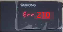 | Pulse Digital | The communication between the encoder and the driver is interrupted after reaching a certain number of times, activating the disconnection detection function. | Check the encoder cable to see if the SD+ and SD- signals are twisted pairs. Connect the encoder line correctly according to the wiring diagram. Correct the incorrect wiring of the connector plug. |
| 3 | Err 40.0 ★Absolute type System power failure abnormality Protect |  | Pulse Digital | The encoder power supply and battery power supply are stopped. The built-in capacitor voltage is lower than the specified value. | Connect the battery power supply and absolute encoder The device performs a clearing operation. |
Platform maintenance
| Serial number | Maintenance content | Diagram | Cause Analysis | Alarm handling method | Alarm handling method |
|---|---|---|---|---|---|
| 1 | The platform needs to be cleaned every day | 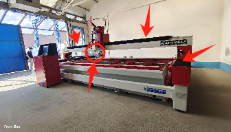 | After the cutting process, sand and water will be splashed on the upper surface of the folded cloth. | It needs to be cleaned in time, otherwise the service life of the folding cloth will be reduced. | It needs to be cleaned in time, otherwise the service life of the folding cloth will be reduced. |
| 2 | The screw guide rail is disassembled and folded for cleaning every month | 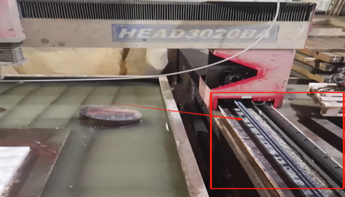 | The lead screw will wear and collect dust during operation . | The folding cloth should be removed and cleaned promptly every month. | The folding cloth should be removed and cleaned promptly every month. |
| 3 | Check the lubrication pump oil level daily | 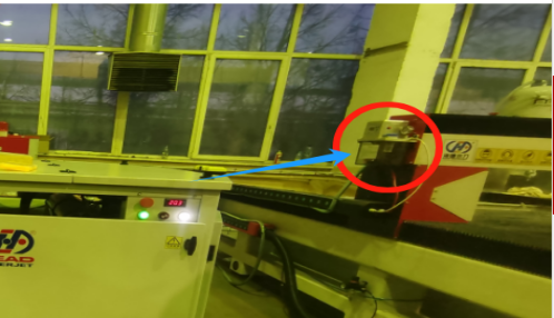 | The lubricating oil pump supplies lubricating oil to the screw guide rail to prevent the screw guide rail from rusting and maintain the service life of the screw guide rail. | The lubricating oil pump supplies lubricating oil to the screw guide rail to prevent the screw guide rail from rusting and maintain the service life of the screw guide rail. | The lubricating oil pump supplies lubricating oil to the screw guide rail to prevent the screw guide rail from rusting and maintain the service life of the screw guide rail. |
| 4 | Clean the dust inside the CNC control cabinet every month |  | During the use of the equipment, dust will enter the control cabinet through the cooling fan, and the static electricity from the dust will cause damage to electrical components, which may even cause a fire. | During the use of the equipment, dust will enter the control cabinet through the cooling fan, and the static electricity from the dust will cause damage to electrical components, which may even cause a fire. | Monthly Cleaning |
Frequently asked questions
| Serial number | Alert content | Diagram | Result reason analysis | Alarm handling method | Accessories pictures |
|---|---|---|---|---|---|
| 1 | Observation hole leaking | 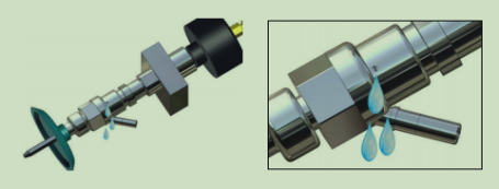 | This causes the pressure to drop, the cutting efficiency to drop, and the low-pressure water enters the sand conveying pipeline, causing sand to get stuck. | Solution: 1. Tighten the cutting head. 2. Replace the water nozzle. 3. Replace the cutter head extension rod. |  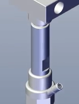 |
| 2 | Water column divergence | 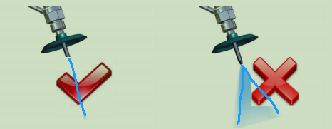 | Cutting efficiency is reduced and metal cannot be cut | Solution: 1. Replace the water nozzle. 2. Replace the sand tube. 3. Replace the cutting head. | 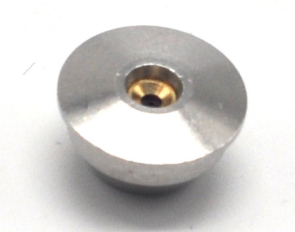 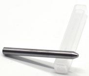 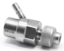 |
| 3 | The observation hole under the water switch valve body is leaking | 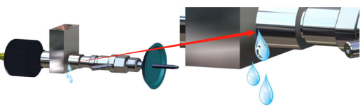 | This causes the pressure to drop, the cutting efficiency to drop, and the low-pressure water enters the sand conveying pipeline, causing sand to get stuck. | 1、 Tighten the tool head extension. 2、 Replace the water switch valve gasket. 3、 Replace the cutter head extension. 4、 Replace the water switch valve body. |  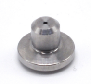 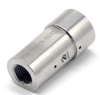 |
| 4 | Water flows out of the sand pipe when the water switch is turned off |  | This causes the pressure to drop, the cutting efficiency to drop, and the low-pressure water enters the sand conveying pipeline, causing sand to get stuck. | Replacement water switch repair kit | 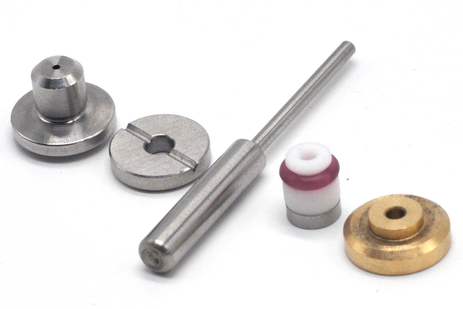 |
| 5 | The observation hole on the water switch valve body is leaking | 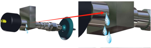 | This causes the pressure to drop, the cutting efficiency to drop, and the low-pressure water enters the sand conveying pipeline, causing sand to get stuck. | Replacement water switch repair kit |  |
| 6 | When the sand control valve is in the closed state, sand still flows out after the bottom is rotated open. | 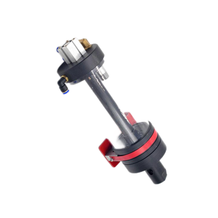 | The sand is out of control and blocks the sand transport pipeline | Replace the sand control valve core and sand control valve block. | 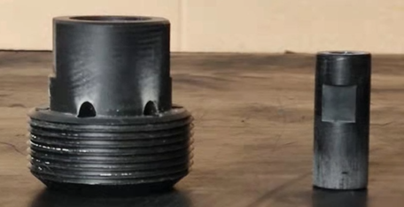 |
| 7 | Operating software backup |  | Software backup path: My Computer - Drive D - BAK folder - Software backup compressed file |